Steam power plant auxiliaries and accessories; (1922)
Croft, Terrell, 1880- ed, Dufflin, Daniel John, 1911- ed · New York, [etc] McGraw-Hill book company, Inc · leaf 112
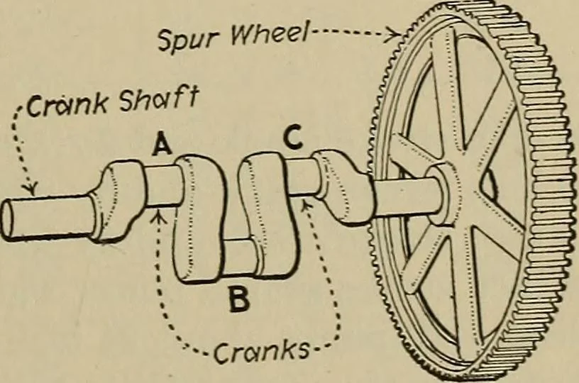
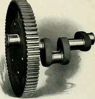
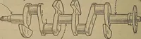
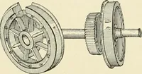
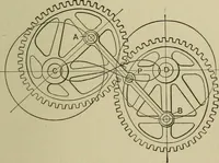
Fig. 115 show the ratesof discharge and suction of each ofthe individual cylinders A, B, and C(Fig. 117) and also of the whole pump.The line XX (Fig. 115) represents the position of the plungers at theinstant considered in Fig. 117. The distances of the points A, B, and Cfrom the line of zero… … -Cranks Fig. 116.—Main Gear And Crank-Shaft Of A Triplex Power Pump. 92 STEAM POWER PLANT AUXILIARIES [Dw. 3 point A is on the zero discharge line. Cylinder B is nearing its maximumrate of discharge as shown by the rise of graph B at B. Cylinder Chas passed its maximum rate of suction, as shown by…
Steam power plants · Pumping machinery
Internet Archive · Library of Congress · Public Domain Mark 1.0. Free to use for anything.