Tappet and dobby looms : their mechanism and management (1912)
Roberts, Thomas · Manchester [Greater Manchester] : Emmott & Co., Ltd. · leaf 94
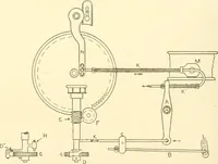
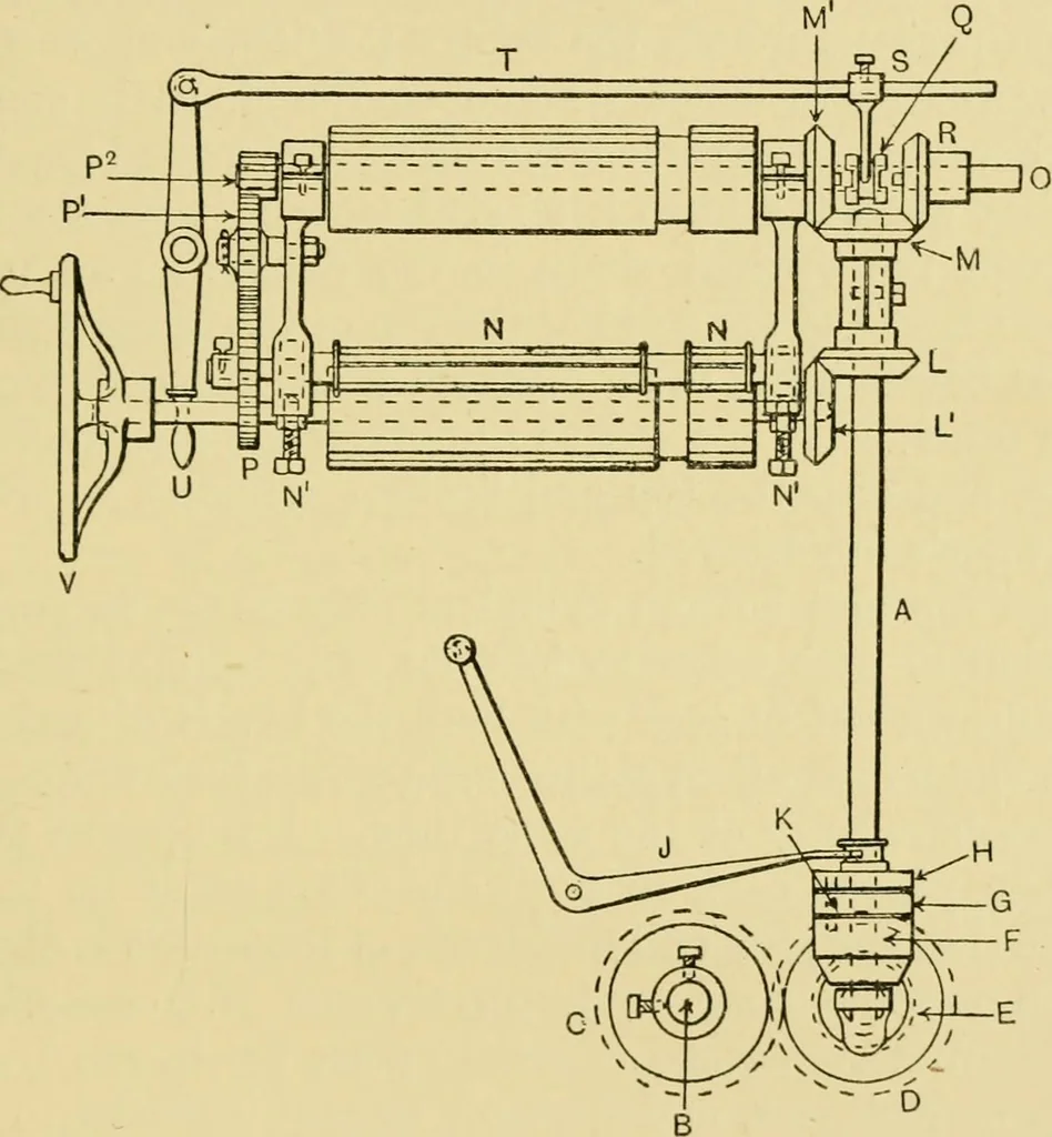
he method of driving the various parts of theHoUingworth and Knowles dobby is illustrated in sideelevation in Fig. 26. The upright shaft A is driven fromthe end of the crankshaft B by the spur and bevel wheels DRIVING THE DOBBY 83 C, D, E, and F. The spur wheels C and D are occasion-ally made… … FiG. 26. necting the dobby mechanism from the rest of the loomto allow the healds to be brought level or the action of thedobby reversed. The clutch box consists of three parts—namely, the clutch-box bevel F, the centre portion G,and the top part H. The bevel wheel F is driven fromthe bevel wheel…
Looms
Internet Archive · UMass Dartmouth, Claire T. Carney Library · Public Domain Mark 1.0. Free to use for anything.
![An illustration from [Graphophone patents] (1878)](https://img.insideoutlibrary.com/img/200/ia-graphophonepaten07unit-453-304.webp)