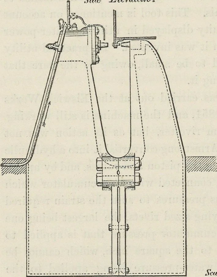
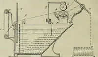
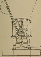
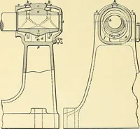
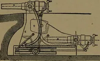
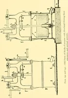
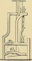
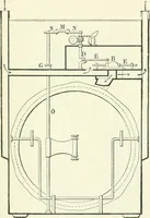
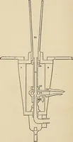
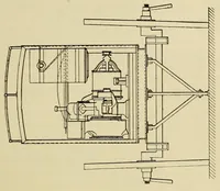
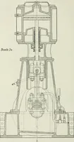
SHOP TOOLS . ICO it into the cylinder of the rivetter , combined with the steady pressure or squeeze due to the load , was established . One of Mr . Tweddell ’ s fixed hydraulic rivetters is shown by figs . 20 to 27 . A side elevation is given by fig . 20 . An end elevation by fig . 21 . Fig . 22… … Fig . 22 . dinal section . Fig . 24 is a back elevation , and fig . 25 is a front elevation . Fig . 26 is a sectional plan of the valve box . Fig . 27 is a longitudinal section of the ram . These illustrations are taken from the Proceedings of the Institution of Mechanical Engineers .
e-rara · Eisenbibliothek Schlatt · No known copyright restrictions. Free to use for anything.