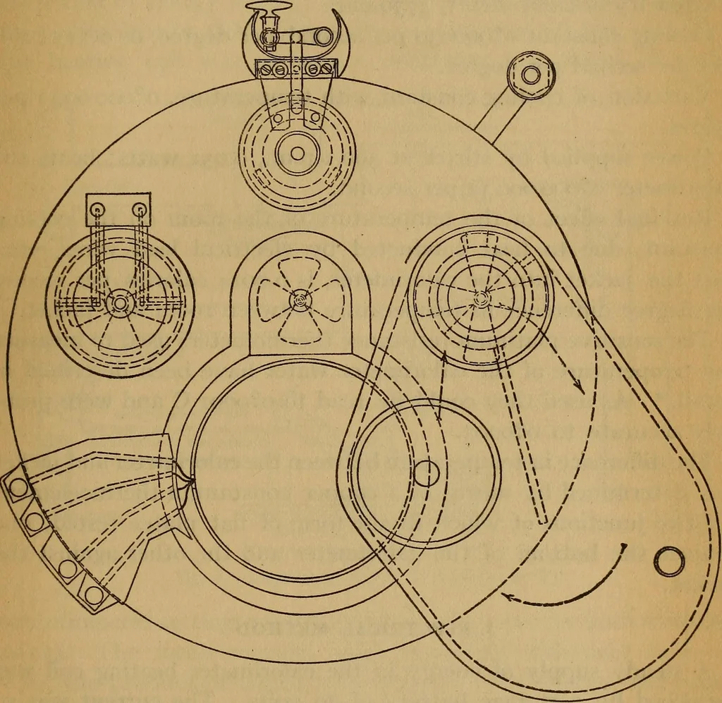
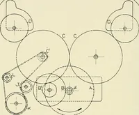
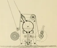
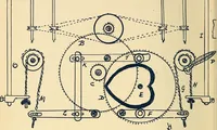
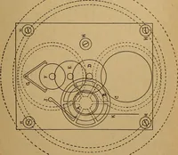
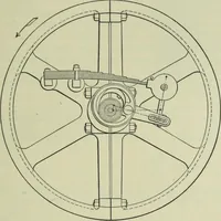
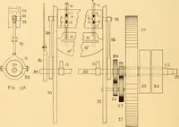
kinson, Harper,Osborne Latent Heat of Fusion of Ice 241 Fig. 3 shows the details of construction, representing a sectionthrough the three stirring shafts. The direction of circulation ofthe water is indicated by arrows. The main jacket stirrer drawswater from the bottom of the jacket, sending part… … Fig. 4.—Plan of calorimeter stirrer to its shaft is also shown. The energy supplied by thestirrer is due to fluid friction only, since there is no bearing withinthe calorimeter. Fig. 4 is a plan of the instrument with the cover open. There are thus realized (1) a well-stirred water calorimeter,…
Specific heat and latent heat · Heat flow, thermal and thermodynamic processes
Internet Archive · NIST Research Library · Public Domain Mark 1.0. Free to use for anything.