Machine drawing; a text and problem book for technical students and draftsmen (1921)
Svensen, Carl L. (Carl Lars), 1884- · New York, D. Van Nostrand company · leaf 130
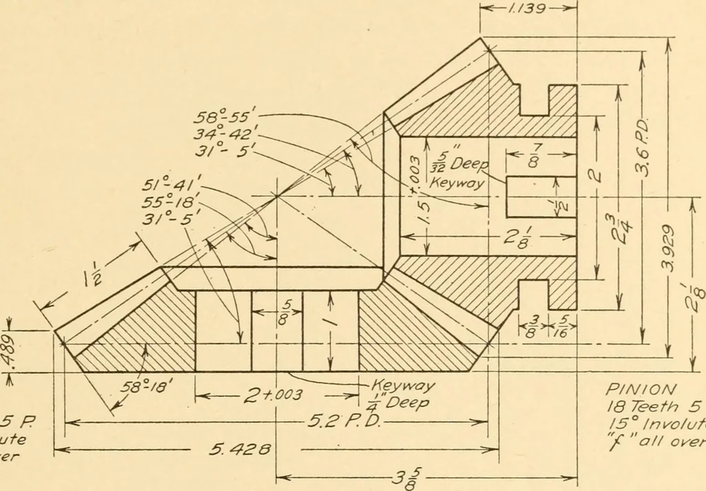
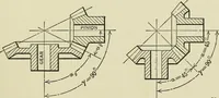
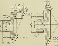
Fig. 207. Bevel Gear Terms. in Fig. 207. Note the location of the pitch diameter and that the ad-dendum and dedendum are measured at the large end of the gear tooth.A bevel gear drawing is shown in Fig. 208. . GEARS AND CAMS 119 58-553/° 5~ GEAR 36 Teeth 5 P/5 ° Involutef all over … P/NION18 Teeth 5P15° Involutey all over Fig. 208. Bevel Gear Drawing. 165. Worm Gearing.—A worm and wheel are shown in Fig. 209. Aworm is a screw having a section on a plane through its axis of the sameform as an involute rack tooth. The gear which is driven by the worm
Machinery
Internet Archive · Library of Congress · Public Domain Mark 1.0. Free to use for anything.