Naval architecture: a manual on laying-off iron, steel, and composite vessels (1898)
Watson, Thomas Henry · London; New York: Longmans, Green and co., [etc.] · leaf 385
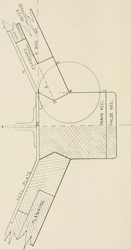
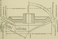
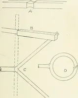
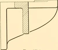
n the corresponding level lines W1 in the Sheer, andpassing a curve through the points W1, etc., so obtained. Form of the Rabbet in the Main Keel Piece.—In Fig. 161from the outer boundary point A describe circle C J B equal in radiusto the thickness of the plank at that part, which is usually… … COMPOSITE VESSELS. 159 main keel piece. Continue inner thickness line F G to cut A C.Then D is the middle of the rabbet. Join D to J, which givesADJ the form of the rabbet for the thick garboard strake. Working Base Line.—Level J extreme height of the circleC J B on to the centre line, then M K is…
Naval architecture -- Handbooks, manuals, etc · Naval architecture · Ships, Iron and steel
Internet Archive · California Digital Library · Public Domain Mark 1.0. Free to use for anything.