Naval architecture: a manual on laying-off iron, steel, and composite vessels (1898)
Watson, Thomas Henry · London; New York: Longmans, Green and co., [etc.] · leaf 76
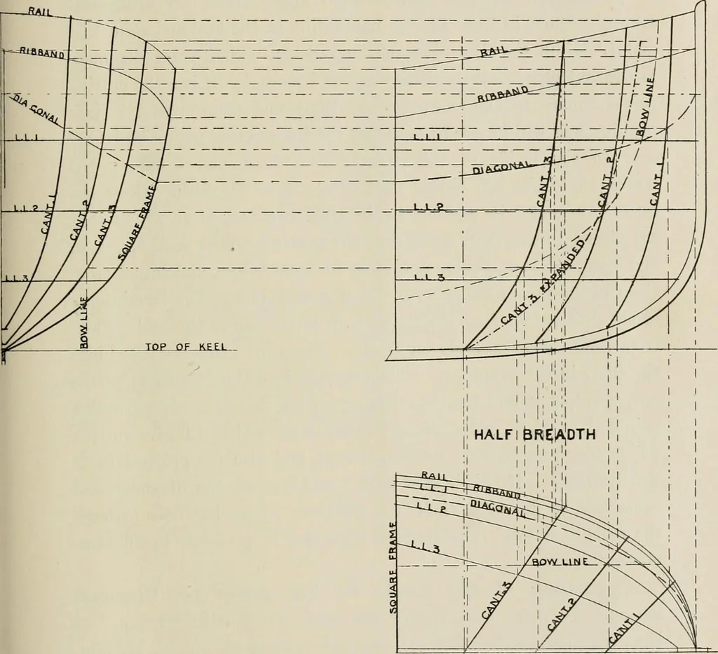
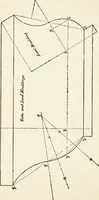
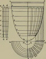
r the true formmay be scrieved in on the scrieve-board, with the true position of theribbands, etc., marked on the scrieves. CANT FRAMES. 29 Projection into the Body.—Square over into the Body the pointsB1 and E1 for the terminations, and set off on A2 B2 the half siding,A2 B3, of the keel at B,… … level lines in the Body. Pass the curve B3 and E3 through the spotswhich will give the required line. The bevelled edge is projected inthe same way; of course, the cutting point on the rail will be slightlyhigher. The cants may not extend to the rail, but it will be evidentthat the rail sheer is…
Naval architecture -- Handbooks, manuals, etc · Naval architecture · Ships, Iron and steel
Internet Archive · California Digital Library · Public Domain Mark 1.0. Free to use for anything.