Lake ship yard methods of steel ship construction (1907)
Curr, Robert · Cleveland : The Marine review · leaf 78
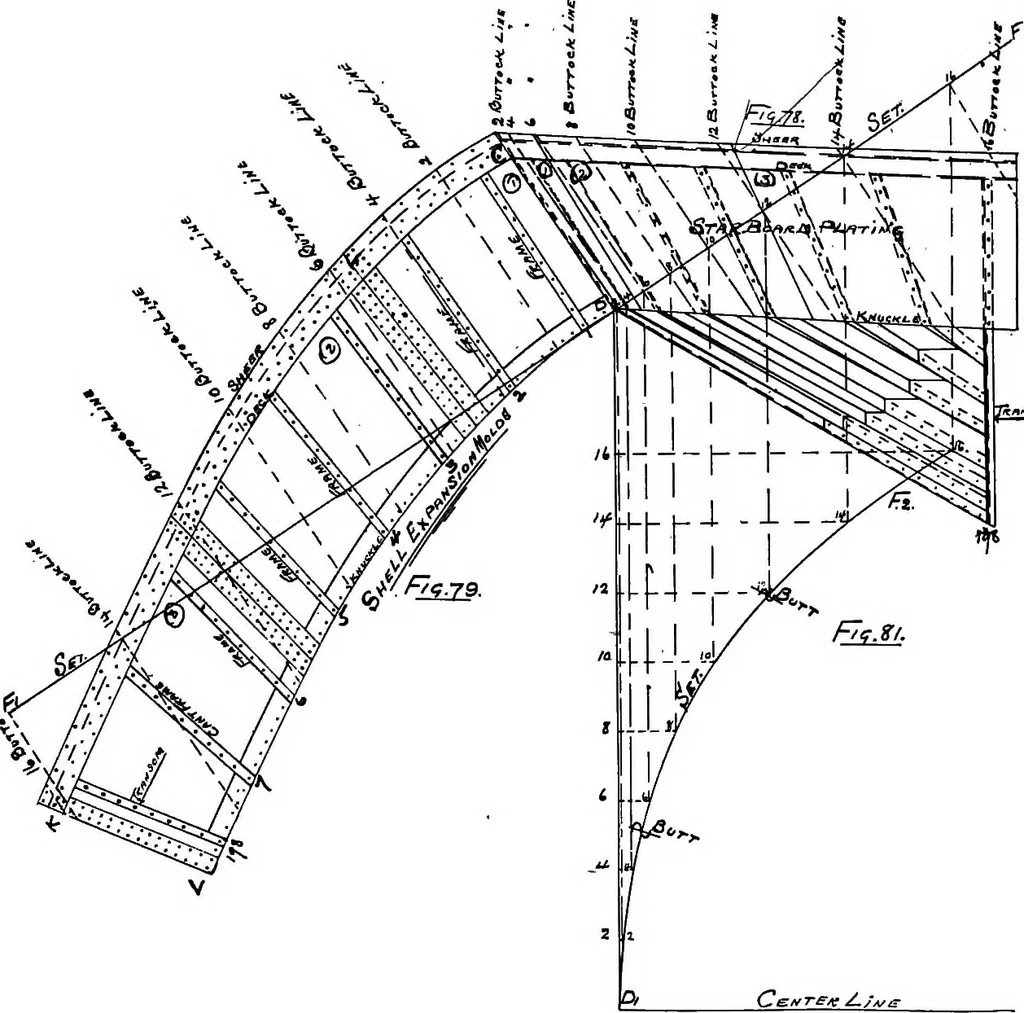
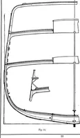
h plan. Fig. 73 shows number 5 cant marked 5 at thetransom, knuckle and deck line, which gives the measurementsreferred to. CANT FRAME BEVELS A, Fig. 77, shows No. 7 cant frame transferred from the sheerplan. Fig. 74, and the expanded cant frame from Fig. 76. X4, X5 STEEL SHIP CONSTRUCTION 67 and… … as shown by X. From X to X2 is the distance for the beveling edgeof the flange, which is measured out on the knuckle line, Fig. 77, asshown at X4. From X to X3, Fig. 73, gives the distance NXS, Fig. 77, the bevel-ing edge at deck. 68 LAKE SHIP YARD METHODS OF To obtain the beveling edge at the…
Naval architecture · Ships, Iron and steel
Internet Archive · Cornell University Library · Public Domain Mark 1.0. Free to use for anything.