Machine drawing; a text and problem book for technical students and draftsmen (1921)
Svensen, Carl L. (Carl Lars), 1884- · New York, D. Van Nostrand company · leaf 210
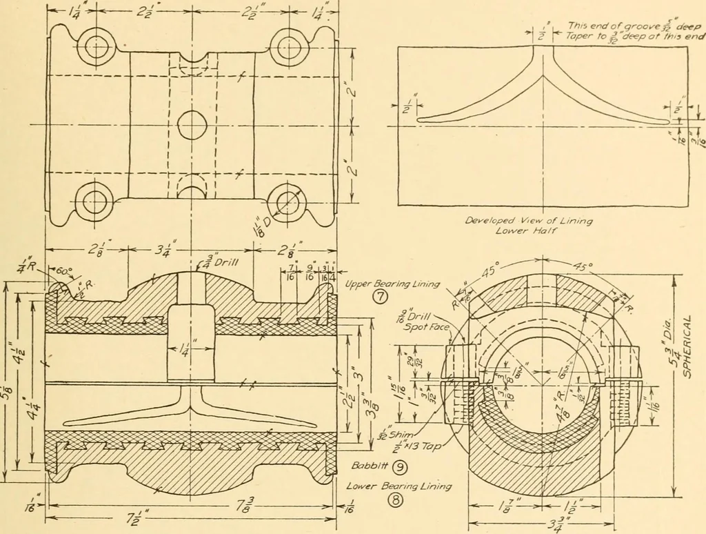
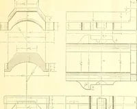
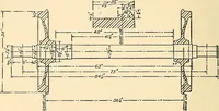
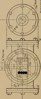
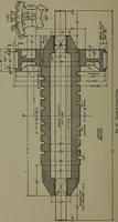
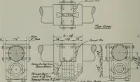
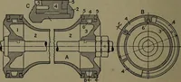
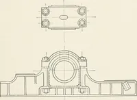
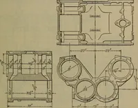
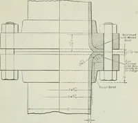
An idea of the assembly may be had by reference to Fig. 73. The adjusting screw(Part No. 2, Fig. 326) is used to screw through the bearing casing cover, causing thespherical seat (Part No. 4, Fig. 326) to grip the Unings (Part No. 7, Fig. 328). Thelock nut (Part No. 3, Fig. 326) is used to hold the… … Fig. 328. Probs. 181 to 184. The list of parts is as follows: 1. Bearing Case Cover, Fig. 326. 2. Adjusting Screw, Fig. 326. 3. Check Nut, Fig. 326. 4. Spherical Seat, Fig. 326. 5. Oil Hole Plug, Fig. 326. Safety Chain for Plug, not shown.No. 8—32 Machine Screw V2 longto hold chain, not shown. 6.…
Machinery
Internet Archive · Library of Congress · Public Domain Mark 1.0. Free to use for anything.